- 您现在的位置:买卖IC网 > Sheet目录1990 > BU2363FV-E2 (Rohm Semiconductor)IC CLOCK GEN DVD-VIDEO SSOP-B16
BU2285FV,BU2363FV
Technical Note
3/16
www.rohm.com
2009.04 - Rev.A
2009 ROHM Co., Ltd. All rights reserved.
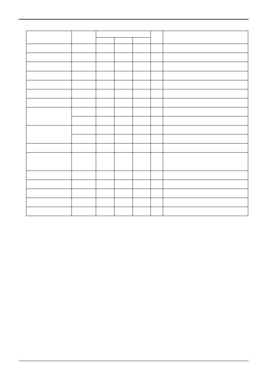
◎BU2363FV(VDD=3.3V, Ta=25℃, Crystal frequency 36.8640MHz, unless otherwise specified.)
Parameter
Symbol
Limits
Unit
Conditions
Min.
Typ.
Max.
Output L voltage
VOL
-
0.4
V
IOL=4.0mA
Output H voltage
VOH
2.4
-
V
IOH=-4.0mA
Consumption current
IDD
-
30
50
mA
At no load
CLK54M
-
54.0000
-
MHz
XTAL×375 / 64 / 4
CLK27M
-
27.0000
-
MHz
XTAL×375 / 64 / 8
CLK33M
-
33.8688
-
MHz
XTAL×147 / 40 / 4
CLK16M
-
16.9344
-
MHz
XTAL×147 / 40 / 8
CLK768FS1
CLK768_H
-
36.8640
-
MHz
At FSEL=OPEN,
XTAL output
CLK768_L
-
33.8688
-
MHz
At FSEL=L,
XTAL×147 / 40 / 4
CLK384FS2
CLK384_H
-
18.4320
-
MHz
At FSEL=OPEN,
XTAL / 2 output
CLK384_L
-
16.9344
-
MHz
At FSEL=L,
XTAL×147 / 40 / 8
Duty
45
50
55
%
Measured at a voltage of 1/2VDD
Period-Jitter 1
σ
P-J 1
σ
-
50
-
psec
*1
Period-Jitter MIN-MAX
P-J
MIN-MAX
-
300
-
psec
*2
Rise Time
Tr
-
2.5
-
nsec
Period of transition time required for the clock
output to reach 80% from 20% of VDD
Fall Time
Tf
-
2.5
-
nsec
Period of transition time required for the clock
output to reach 20% from 80% of VDD
Output Lock-Time
Tlock
-
1
msec *3
C/N 54M
-65
-80
-
dB
*4
(At a maximum load)
C/N 33M
-50
-60
-
dB
*4
(At a maximum load)
Note) The output frequency is determined by the arithmetic (frequency division) expression of a frequency input to XTALIN.
If the input frequency is set to 36.8640MHz, the output frequency will be as listed above.
Common to BU2285FV and BU2363FV:
*1
Period-Jitter
1
σ
This parameter represents standard deviation (
1 σ) on cycle distribution data at the time when the output clock cycles
are sampled 1000 times consecutively with the TDS7104 Digital Phosphor Oscilloscope of Tektronix Japan, Ltd.
*2
Period-Jitter
MIN-MAX
This parameter represents a maximum distribution width on cycle distribution data at the time when the output clock
cycles are sampled 1000 times consecutively with the TDS7104 Digital Phosphor Oscilloscope of Tektronix Japan, Ltd.
*3
Output Lock-Time
The Lock-Time represents elapsed time after power supply turns ON to reach a 3.0V voltage, after the system is
switched from Power-Down state to normal operation state, or after the output frequency is switched, until it is stabilized
at a specified frequency, respectively.
BU2363FV
*4
Make measurements with settings of SPAN to 100kHz, RBW to 1kHz, and VBW to 100Hz taking the middle point
between (54.0000MHz
20kHz) and (33.8688MHz20kHz) as a measurement point.
发布紧急采购,3分钟左右您将得到回复。
相关PDF资料
BU2365FV-E2
IC CLOCK GEN W/VCXO SSOP-B24
BU2505FV-E2
IC DAC 10BIT 10-CHAN SSOP-B20
BU2508FV-E2
IC DAC 10BIT 4-CHAN SSOP14
BU3076HFV-TR
IC CLOCK GEN 1CH HVSOF6
CA3338AMZ96
IC DAC 8BIT 50MSPS R-R 16-SOIC
CDCR83DBQG4
IC DIRECT RAMBUS CLK GEN 24-QSOP
CDP68HC68T1M
IC RTC 32X8 NVSRAM CMOS 20-SOIC
CPLL66-1600-2200
IC VCO PLL/SYNTH 2.2GHZ SMD
相关代理商/技术参数
BU2363FVFV-E2
制造商:ROHM 制造商全称:Rohm 功能描述:DVD-Audio Reference Clock Generator for Audio/Video Appliance
BU2365F-E2V
制造商:ROHM 制造商全称:Rohm 功能描述:Clock Generator with Built-in VCXO for Audio/Video Equipments
BU2365FV
制造商:ROHM 制造商全称:Rohm 功能描述:Clock Generator With Built-in VCXO
BU2365FV_08
制造商:ROHM 制造商全称:Rohm 功能描述:Clock Generator with Built-in VCXO for Audio/Video Equipments
BU2365FV-E2
功能描述:时钟发生器及支持产品 CLOCK GEN W/VCXO A/V EQUIPMT RoHS:否 制造商:Silicon Labs 类型:Clock Generators 最大输入频率:14.318 MHz 最大输出频率:166 MHz 输出端数量:16 占空比 - 最大:55 % 工作电源电压:3.3 V 工作电源电流:1 mA 最大工作温度:+ 85 C 安装风格:SMD/SMT 封装 / 箱体:QFN-56
BU2370FV
制造商:ROHM 制造商全称:Rohm 功能描述:VCO + phase comparator for TV
BU2373FV
制造商:ROHM 制造商全称:Rohm 功能描述:VCO & Phase-Detector for PLL System
BU2373FV_11
制造商:ROHM 制造商全称:Rohm 功能描述:High Performance VCOs for Image Sampling